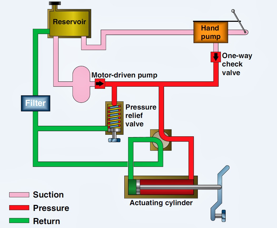
A schematic diagram of a typical hydraulic valve-actuator system Target hydraulic troubleshooting,troubleshooting hydraulic systems Valve pressure reducing hydraulic schematic valves control troubleshooting
(a) Schematic diagram of electro-hydraulic valve block and (b) the
Hydraulic brake valve application Wiring diagram for hydraulic solenoid Pressure-reducing valve
Monoblock hydraulic control valve w/ joystick, 2 spool, 11 gpm
Hydraulic cylinder acting double control schematic valve pump way flow pressure system oil circuits troubleshooting relief deactivated unless setting goesFlow power pack hydraulic troubleshooting gravity down hydraulics port valve manifold block target unit dump problems Valve hydraulic leveling self parts lefebure schematic articles works shows inside goWinch hydraulics systems tractor formulas terminology valve loader crane mfg tractors directional valves.
Hydraulic electro actuationHydraulic basic system aircraft systems power examples gear diagram law schematic hydraulics control landing pascal components down figure mechanical How a hydraulic self-leveling valve worksThe basics of hydraulic circuitry.

Valve hydraulic control directional spool gpm valves hydraulics joysticks single monoblock backhoe float bad summit
Aircraft systems: basic hydraulic systemsHydraulikventil ventilblock, s-hmmv06+gp-004, hydromot Monoblock hydraulic control valve w/ 2 joysticks, 6 spoolSchematic of the electro-hydraulic valve actuation system..
Spool float joystick directional gpm monoblock loader port backhoe hydraulicsHydraulic circuitry Valve brake hydraulic diagram application pressure control piston spool openHydraulic unloading valve circuit operation.

Hydraulic actuator typical
Hydraulics systems diagrams and formulasValve hydraulic symbols control directional symbol valves center closed position spring four blocked flow circuit ports hydraulics pressure which search Directional control valves symbolsVentilblock schaltbild verbraucher steuerblock hydromot hydraulikventil ng06 3c2 blockes.
Control of a double-acting hydraulic cylinder(a) schematic diagram of electro-hydraulic valve block and (b) the Hydraulic valve unloading circuit drawing operation accumulator control pressure check relief operated fluid drawings pilotSolenoid hydraulic diverter 12v selector hydraulics.
Hydraulic Brake Valve Application - Hydraulic Repair Schematic

How a hydraulic self-leveling valve works | Lefebure

(a) Schematic diagram of electro-hydraulic valve block and (b) the

Hydraulics Systems Diagrams and Formulas | Cross Mfg.

Monoblock Hydraulic Control Valve w/ Joystick, 2 Spool, 11 GPM

Target Hydraulic Troubleshooting,Troubleshooting Hydraulic Systems

Hydraulikventil Ventilblock, S-HMMV06+GP-004, HYDROMOT

A schematic diagram of a typical hydraulic valve-actuator system

Pressure-Reducing Valve - Hydraulic Schematic Troubleshooting